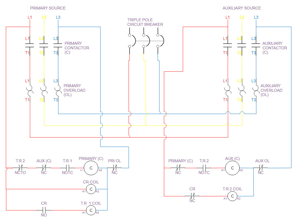
Carrying a rated current and switching the connection from one power source to another are the responsibilities of an automatic transfer (changeover) switch. This lesson teaches how to build an automatic transfer switch using contactors, control relay, overload relays, and timer relays. When there is a power outage or fault on the primary source, this automatic transfer switch circuit can be used to transfer power to the backup or auxiliary source, but before this can happen, the timer delays the transfer because, when using utility power, the automatic transfer logic must react to a "source abnormal" signal. In order to avoid a needless transfer, this response is typically delayed to ensure that the aberration is not a transient condition.
 |
| Three phase automatic changeover switch using contactors |
 |
| Single phase automatic changeover switch using contactors |
The function of each element's part
Contactors: These contactors are used to energize and de-energize the distribution panel using electromagnetism. It creates a path for current to flow to loads connected to the distribution panel through its contacts, which are closed while the coil is energized and open when the coil is de-energized
Control relay: The control relay is used to energize timer relay one (1) coil and de-energize timer relay two (2) coil.
Overload relays (block): The overload relay is used to guard against the excessive current flow in loads connected to the automatic changeover switch.
How does it work?
When the primary power source is present, the current will start to flow through the control relay (CR) coil and produce an immediate magnetic field. This magnetic field then opens the normally closing control relay (CR) contact, disabling the energization of the timer relay two (T.R 2) coil. The control relay (CR)'s magnetic field also caused the normally open control relay (CR/NO) contact to close, which created a path for the current to flow to the timer relay one (T.R 1) coil.
Due to the on delay function, the timer relay one (T.R 1) will take five minutes to alter the state of its contacts. The normally open time closed (NOTC) contact will close once the timer relay one (T.R 1)'s preset time has passed. This will create a path for the current to flow to the primary contactor coil and close the primary contactor's main contacts, which are wired to send power to the load connected to the breaker from the primary source.
The control relay coil will de-energize when the primary power supply is absent, which will re-open the closed contact (CR/NO) that was closed when the control relay (CR) coil was energized and de-energized the timer relay one (T.R 1) coil. The normally open time closed (NOTC) contact, which is closed due to the energization of timer relay one (T.R 1) coil used to energize the primary contactor coil, will revert to its open state as soon as T.R 1 coil loses power, de-energizing the primary contactor coil and re-opening the primary contactor main contacts.
As soon as timer relay one's (T.R 1) coil loses power, the normally closed time open (NCTO) contact will return to its closed state, creating a path for current to flow to timer relay two's (T.R 2) coil. Once this occurs, it takes five minutes for timer relay two to activate and close out the timer relay two (T.R 2) normally open time closed (NOTC) contact, which is then used to energize the auxiliary contactor coil. Auxiliary contactors are wired to transmit electricity to the load connected to the breaker from an auxiliary source, and when they activate, they close their main contacts.
Due to the control relay coil that is directly linked to the primary source and is used to switch between the auxiliary and primary power sources when the primary power source is available, the circuit is then switched back to the primary power source whenever the primary source returns. Electrical interlocks prevent the operation of both the primary source and the auxiliary source at the same time by wiring the primary contactor coil in series with the normally closed contact on the auxiliary contactor and the auxiliary contactor coil in series with the normally closed contact on the primary contactor.
The overload relays auxiliary (aux) contacts are wired in series with the coils then to line three (3) in order to complete the circuit and provide overload protection if there is excessive current flowing in the circuit. If the current surpasses the amount allowed by the main overload contacts then the overload auxiliary (AUX OL) contacts which are normally closed would open, thus de-energizing the coil circuit.
The circuit can also be wire using phase monitors an illustration of this is displayed underneath


.png)
.png)

.png)
13 Comments
Very well written article on automatic connection
ReplyDeleteI appreciate you very much.
DeleteRegistration photo link The article Automatic switch switch using contactor is very detailed
ReplyDeleteMany thanks
Deletewell written article.
ReplyDeleteMuch appreciation I'm happy you found it informative.
DeleteI loved the way you explained it with pictures
ReplyDeleteI'm happy to hear that you found it enjoyable.
DeleteA very instructive article. Thank you
ReplyDeleteThis information is very rare to find on google, very well explained! Thank you
ReplyDeletePerfectly written article
ReplyDeleteI really like your website
ReplyDeletePlease, this is a very detailed explanation, but please, kindly show the pictures on how it's connected, I meant both single and three phase connections.
ReplyDeleteThanks.
We'd love to hear from you! Share your questions, thoughts, or feedback on this post. Your input helps us create even better tutorials. What topics would you like us to cover next?